Suggestions to improve my ductwork layout?

Status
Not open for further replies.

Rushton

Rush
Senior User
I've posted this on the Clear Vue Cyclone Forum and know we have some members who visit there, but I thought I'd post here because of all the good discussions from members here. I've received my CV1800 (with 16 inch impeller) and am now designing the ductwork layout. I'd appreciate any suggestions for how I might improve my proposed layout and have attached screen shots of my Sketchup layout.

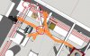
My shop is a small basement shop with low ceilings (7' to bottom of floor joists) and has hot water heating pipes running around the perimeter about 9" below the floor joists. I'm also having to work around the furnace, hot water heater and all of that related plumping. Nonetheless, this should provide a good space for a small hand tool woodworking shop with a limited number of machines. The principal machines that I expect to use quite regularly are: Radial Arm Saw (no table saw), bandsaw, drill press and router table. I may someday add a benchtop planer, a lathe, and downdraft table for sanding. My goal is to capture as much dust as possible right at the source and minimize any micro dust particles escaping into the general air which is shared with the rest of the house.

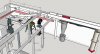
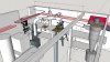
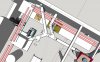
Constraints I must work around are the heating pipes (shown as pink tubes), a water line I am not allowed to re-route (shown as a green tube), and some I-Beams that support the floor joists (the design calls for situating the CV1800 in between those parallel I-Beams with the motor sticking up between the joists). FWIW, the exhaust will be through 8" insulated HVAC flexible duct to the filter stack.

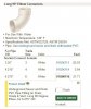
I'm trying to follow Bill Pentz's recommendations of (a) 6" pipe all the way to the machine, (b) a minimum 4 feet run of straight pipe to the cyclone intake, (c) long straight runs of duct with gentle transitions. The 90 degree elbows are all long sweep elbows with 12 inch radius (2X the pipe diameter) which Bill seems to think are good. The transition to the ceiling level main duct line (first Wye) from the straight pipe from the cyclone inlet will be a Fernco flexible coupling. All of the pipe will be 6-inch diameter PVC ASTM 2729 "Sewer and Drain (S&D)". I've chosen to go with the long sweep 90 degree elbows due to space constraints but more importantly due to the hope that the smoother walled surfaces will have less turbulence than double-45s, but I'm certainly no expert on this.

I still have to figure out connections to the machines (hoods, shrouds, etc), but that is a next phase after I get the dust collector and main ductwork installed.

Thanks for looking and for any suggestions you can share.
Rush

attachment.php
attachment.php
 

Attachments

  • cv1800-ductwork-design1.jpg
    cv1800-ductwork-design1.jpg
    177.3 KB · Views: 442
  • cv1800-ductwork-design2.jpg
    cv1800-ductwork-design2.jpg
    175 KB · Views: 433
Last edited:

KenOfCary

Ken
Staff member
Corporate Member
It looks pretty well thought out to me at this point. Are the positions of the machines set in stone yet or can they be made to be more in a straight line to minimize the Wye's?
 

Rushton

Rush
Senior User
Hi Ken, thanks for taking the time to look and reply. All of the machines can be re-located. The machine positions I've selected for the drawing are my to attempt keep the runs as simple as I can, with runs as straight as possible. But let me see if I understand what you're suggesting...

If I line up all the machines and have a straight line for the main duct, won't I still have to pull a Wye off of that straight duct for each machine? Four machines with a Wye for each for four Wyes in total?

If I could get a straight run of pipe along that long wall behind the Radial Arm Saw, then I could place the Wyes directly into the down drops (with a 45 degree elbow) and eliminate those multiple 90 degree elbows for the down drops. That would certainly simplify the airflow. Great idea! But, I can't get there. The angle I need to take off of the cyclone won't clear those furnace hot water pipes and still get 4 feet of straight pipe into the cyclone intake. I played around with the design quite a bit to see if I could make that work, but no luck. (This convoluted ducting I was anticipating is why I upgraded to the 16" impeller on the cyclone - it adds 20-25% additional airflow according to Cathy at Clear Vue.)

Again, THANKS for thinking about this with me. All thoughts are welcome and a big help as I continue to noodle on an optimal solution given the constraints I'm working with.
 

MarkE

Mark
Corporate Member
I went through this when setting up my DC a while back. I finally made the decision to just get all of my machines placed where I wanted them and just run duct to each of them where they sit. Over time I have replaced/added/upgraded machines and changed machine locations, and each time had to re-do the DC pipes. Its very difficult to plan the optimum layout for right now, and almost impossible to plan for future unknowns.

You can spend an awful lot of time trying to come up with the best possible layout, but in the end, all of your planning may be for naught. Do the best you can in the space you have knowing that you are collecting as much of the dust as possible for your situation.

Besides, you have a Clearvue cyclone. If you set your system up too efficiently, you may accidentally suck in some of your smaller machines, or one of your pets. :gar-La;
 

Rushton

Rush
Senior User
Haha... :) Thanks, Mark. I can well imagine the ductwork will change over time as my thoughts or the shop changes. I plan to keep the ductwork easy to disassemble. Rather than taping every joint with aluminum tape, I'll do that for critical junctions but use self-fusing silicone tape or flexible caulking cord for most joints.
 

KenOfCary

Ken
Staff member
Corporate Member
You seem to be on the right tract to planning this. It will be a process - I changed it at least once in my old shop and am still analyzing what will happen in the new shop. Good luck on finding the optimal solution. It will be a process rather than a final solution. It evolves.

If you choose to use metal duct work, consider using this stuff to seal it from air leaks - I really like this stuff and it is very cheap.

https://www.lowes.com/pd/Design-Polymerics-64-fl-oz-Gray-Duct-Sealant/3736193
 

Rushton

Rush
Senior User
If you choose to use metal duct work, consider using this stuff to seal it from air leaks - I really like this stuff and it is very cheap.

https://www.lowes.com/pd/Design-Polymerics-64-fl-oz-Gray-Duct-Sealant/3736193

Good to know of a good sealant for metal ductwork. I have some HVAC ductwork that could benefit from this. But for my dust collection system, I'm committed to working with PVC.

As you observe, this must be an evolving process. I appreciate the feedback that I'm not completely off-track as I get started on this.
 

Rushton

Rush
Senior User
Hi Chris, that does appear strange, doesn't it? The cyclone is at the right hand edge of the space I have available to me for my workshop. The I-Beam to the right of it marks the far extent of "my shop space". I do have the 8" flex exhaust ducting running to the right where the filter stack would be.

The cyclone can't be placed along the front wall (the wall on which the RAS sits) because of furnace hot water pipes (shown in pink) going through that space. And, because of my low ceiling, the motor has to fit up between the ceiling joists and this is where there is vertical open space to allow for that.
 
Last edited:

McRabbet

Rob
Corporate Member
Rush,

I saw your post on the CV Forum as well and will duplicate this entry there. It appears you have a good layout considering the overhead constraints that you face with beams, pipes and ducts. I agree with using S&D PVC for your ductwork and suggest that you use a 6" x 6" Fernco coupling like this one from Lowes for the connection shown in the long straight run to the cyclone intake. It will make the gentle bend and reduce vibration. I would also recommend using clear silicone caulk at each fitting; in general, they are tight enough that they won't leak. I use the CV blast gates at the machine end of each drop and connect to 6" flex that I bought from McMaster-Carr. I use galvanized pipe hanger strap to hold my duct in the air where needed.
 

Rushton

Rush
Senior User
Hi Rob, thanks for taking a look and providing me with some suggestions. BTW, I have the bin full sensor from Clear Vue that you designed and will be installing it as well.

Great suggestion to use the 6x6 Fernco coupling at the point of that bend to horizontal at the end of the cyclone intake pipe - I have one on order. I'd seen the recommendation to use one in the CV Forum and thought it made great sense.

I have clear silicone caulk for the cyclone joints but am a bit hesitant about applying it to my ductwork joints because I'm sure I will end up changing things around as I figure out dust shrouds and re-arranging machine locations. How difficult is it to pull apart piping joints once silicone caulk is applied? As an alternative for those joints that may get pulled apart down the road, I thought I'd use either flexible self-fusing silicone tape that will cut away without leaving any residue OR flexible caulking cord like this M-D caulk available at Home Depot.

When fitting the blast gates for each machine, is there any value in placing them as close to the main truck line as possible rather than next to the machine? In other words, close off as much volume in the unused drop as possible? Or does it not make any practical difference? I have blast gates for each machine that I ordered from Clear Vue with the cyclone.

The galvanized strap hangers seem to be a good simple solution. I decided to try the alternative of using 48" nylon zip ties and anchors a Bill Pentz suggested. The biggest challenge with the zip ties is undoing them to reposition. It can be done with a small probe to flip back the locking lever, but can be a pain to accomplish. But I like the ability to apply them loosely and then tighten them to get the desired fit once a row of pipe and fittings are lined up.
 

Alan in Little Washington

Alan Schaffter
Corporate Member
Rush- before I talk about your layout, you do realize that a CV1800 is total overkill for the machines you have and size of your shop?!?!

I know you are limited by the low joists, etc. but there are a few things you might be able to do to simplify the layout and improve flow.

First, that triple wye is a real turbulence generator and should go. The run to your drill press has a 45° and 2 90° elbows - 90° elbows are tough on SP and CFM. Run your main line right to (just a tad short of) the opposite wall and come off the end with a 45° wye angled down to the wall then another 45° to the drill press. Run a single 45° to the left to the bandsaw- instead of a 90° come off that with a 45° angled down and another 45° either one after the other or separated by a few feet of straight. Run one 45° off the main to the right then 45 off the bottom that runs down a wye- one branch to the router table and once to the radial arm saw. I may have missed them but I have never seen nor even heard of long sweep elbows in ASTM 2729. Hopefully, below is a (very) rough sketch of what I mean.

Put your blast gates next to the machine/where easiest to reach. A drop with a closed blast gate at the tool end is invisible to the system- absolutely no impact on SP or CFM. No need to put the blast gates near the main.

Last, but not least and of UTMOST IMPORTANCE!!!! Are your furnace or hot water heater gas or oil fired and not electric and are they located in the basement or near the shop? If so, do they have standard flu vents (not sealed fireboxes with PVC, fan powered direct venting) If so you have a potentially DEADLY situation with the DC pulling flu gases containing CARBON MONOXIDE, in the reverse direction back into your shop!!!!!
 

Attachments

  • DCpipe.jpg
    DCpipe.jpg
    216.5 KB · Views: 194

Rushton

Rush
Senior User
Hi Alan, thank you for taking the time to look at this and offer good helpful suggestions, and questions! Yes, the CV1800 is arguably overkill. But I'm committed to keeping the fine dust out of my lungs and out of the rest of the house, so I consider it a worthwhile "overkill".

To your main caution and concern, yes: this space is shared with a traditional gas fired hot water heater and furnace with conventional flue. I hear your concerns about pulling flue gases into the shop and this is the reason I do not vent to the outside. I'll put carbon monoxide monitors in the shop to keep a watch on the issue.

With respect to your ducting suggestions: all great! right on point. I debated about the triple Wye and whether two regular Wyes in series would be better. What I'm hearing you say is that if I have to keep the current design, DITCH the TRIPLE Wye and put two Wyes in series. Correct?

As to the drill press, I'd love to do what you suggest in your attached sketch and take the main line all the way to the drill press. Unfortunately, there is a water pipe right in the way (shown as a green tube in my sketch). My wife is very tolerant of my excesses, but she's been adamant that I may not move any of the plumbing in the house. I have to fit myself around it however I can. Left to my own devices, I'd cut and re-route that water pipe to get it out of the way so I can pull the duct all the way to the drill press. This will have to be one battle at a time - I may still win this one, but the discussion must wait for another day.

Thanks for your recommendation to simply put the blast gates next to the machines. I did not know whether they should be closer to the Wye for the drop line or whether they would be fine if placed close to the machine. I hear your message that "A drop with a closed blast gate at the tool end is invisible to the system- absolutely no impact on SP or CFM. No need to put the blast gates near the main."

The long sweep 90s may not be ASTM 2729, the online seller does not specify. They are these and have a 12" centerline radius per the spec drawings. I'm using the 2X Diameter Radius elbows per the information on ductwork connectors provided by Bill Pentz at his website here.

Thanks for sharing all of this information, Alan. I'm learning and open to hearing what people are willing to offer.


Last edited:

Alan in Little Washington

Alan Schaffter
Corporate Member
Not venting outside? Are the filters in another room with a door? That can be almost as bad.

Does your drawing show 2 representative joists or are they beams? Looks like beams to me due to rectangular lolly column- which direction do the joists run? If the water lines are attached to the bottom of and perpendicular to the joists, can't you run duct above them in the joist bay? If not how much of a joggle would the pipe need to get under the water lines so you could run the main to the drill press? Will that reduce headroom too much? If you can't do that and can't go straight, there still is absolutely no need for a 3-way wye. Just use two wyes in a row.

I still really do not like your DP run. Will you need to be able to walk between the cube structure next to the bandsaw (is that the furnace?) and the wall? If not, put a wye at the bottom of the bandsaw drop and run a low height duct to the DP.

You didn't provide enough dimensions to do a good evaluation, but another option is to move the DC to the right end of the miter saw bench and a little bit into the space where you show the filter flex duct. Remember, everything on the discharge side- duct, fittings, filter, etc. - after the blower, has the exact same negative effect on performance (SP & CFM) as all the stuff on the suction side of the "system" ? Flex is not the best type of duct to use here if you can avoid it! To what and how are you planning to mount the DC?

What is the grade outside that window? If you have enough space- why not put the DC outside. Depending on type, open or remove the window and run suction and return ducts through an insulated ply panel. That is what I did when I had a small basement shop like yours. If you have neighbors you may need a sound reducing enclosure.

Lastly, I may be wrong,, but I'm pretty certain the fittings you are looking at on that website are for Sched40/80 NOT for ASTM 2729! The website is lacking info and doesn't provide I.D. specs for the fittings. Remember Sched 40, 80, SDR-35, and ASTM 2729 are all types of DWV ("drain, waste, and vent"). However, ASTM 2729 and the slightly thicker walled SDR 35 (same O.D as ASTM 2729) have a different O.D. (and I.D.) than Sched 40/80 so you must use different fittings. They sell ASTM 2729 pipe- theirs is gray and they call it "PVC-PIPE-DUCT-thin wall", but I was not able to find fittings for that pipe on their website. Also, their price per foot is outrageous! Lowes, carries 6" fittings (3034/3035) that fit ASTM 2729- it is in the irrigation area, not the plumbing area (manufacturer: NDS?). Fittings come in PVC and styrene, and are much cheaper than Sched 40 fittings. You may also be able to find ASTM 2729/SDR34/SDR35 fittings at Menards, ACE, McMaster-Carr, etc.
 

Rushton

Rush
Senior User
Alan, I appreciate your efforts to help me think about this. Sorry if I'm making it frustrating for you. I'll try to answer you questions interspersed below in blue.

Not venting outside? Are the filters in another room with a door? That can be almost as bad.
The filters are in the same room and sharing the same air space, just off into an extended portion of the room to the right of the I-Beam. That is space for other purposes but I am able to set the filters in a corner and run the 8" exhaust duct (insulated HVAC flex) along the wall to the filters.

Does your drawing show 2 representative joists or are they beams?
They are I-Beams, as you surmise. There is 9 1/2" of joist space above them, some of the joist space is clear, some not. The motor for the collector will be pushed up into the joist space to acquire the height needed for it.

If the water lines are attached to the bottom of and perpendicular to the joists, can't you run duct above them in the joist bay?
The water line does run perpendicular to the joists and I do have space above the water line to bring the duct through one of the joist bays (just went downstairs to measure). Since the joist bays run parallel to that main duct, I would just have to jog it left or right a bit to get it centered under one of the bays, which I think I could do. But then I'd have to use two 45s to bring the duct up into the joist bay to carry it over the water pipe. I assume you think introducing two 45s to come up and over the pipe in order to bring it to the wall behind the drill press would be an improvement over meandering around the room perimeter as currently shown. Correct?

Of course, even better would be to run the main duct straight to the drill press by changing that water line and moving it out of the way of the duct.

And, we are agreed to eliminate the Triple Wye from the design. Regardless of the ultimate resolution of the ductwork to the drill press, I'll eliminate that Triple Wye.

You didn't provide enough dimensions to do a good evaluation, but another option is to move the DC to the right end of the miter saw bench and a little bit into the space where you show the filter flex duct.
There isn't enough headroom between the joists in that location to allow the motor to sit between the joists to get the needed height. Some other piping not readily shown in my sketch make it unlikely to get the first several feet of duct aligned for a straight run to the intake.

Remember, everything on the discharge side- duct, fittings, filter, etc. - after the blower, has the exact same negative effect on performance (SP & CFM) as all the stuff on the suction side of the "system" ? Flex is not the best type of duct to use here if you can avoid it!
I've worried about this issue. The purpose of the insulated HVAC flex for the exhaust is to provide some noise reduction. I've read that 8' to 20' of insulated HVAC flex on the exhaust provides a fair amount of noise reduction. But, I'd accept more noise over a material reduction in performance. I don't have quite the height I need to mount the filter stack using Clear Vue's standard 90 degree transition, so I have to separate the filter stack. I thought the flex duct might do the trick with the added benefit of some noise reduction. I've seen photos of a number of workshops using an extended run of 8" flex to the filter stack and haven't yet read many negatives to doing this until your warning.

To what and how are you planning to mount the DC?
It will be mounted on an independent free-standing lumber and plywood structure that I will build, sitting on the concrete floor but not otherwise attached to the house structure.

If you have enough space- why not put the DC outside.
The bottoms of the windows you see in the drawing are at grade, so it would be possible to place the DC in a separate shed outside as you did in an earlier workshop. But, this is not something I want to consider as long as I can find an acceptable "in-the-workshop" solution. If I understand what we're saying, doing this solves some space and noise issues for the cyclone itself, but still doesn't resolve the reverse flue draw concern with the conventional furnace and hot water heater in the same space as the shop. (BTW, my plumbing and HVAC guy is coming to the house tomorrow on another matter, so I will discuss this issue with him while he's here.)

Lastly, I may be wrong,, but I'm pretty certain the fittings you are looking at on that website are for *Sched40/80 NOT for ASTM 2729*!
I'm not surprised, but disappointed. If the fit is just not workable, I'll have an expensive return or re-sale to manage. I thought the specifications for Schedule 40 and ASTM 2729 called for the same outside diameters but different inside diameters. But if I'm wrong, I'll just have to punt on the 90s and go to double 45s. I have a local plumbing supply company that carries ASTM 2729 6" pipe and some of the standard fittings and I plan to get my pipe from them.

Thanks, Alan. I'll take a hard look at improving that run to the DP. I may defer running that portion of the ductwork until I can talk my wife into letting me just re-route that water pipe.
 

Alan in Little Washington

Alan Schaffter
Corporate Member
Alan, I appreciate your efforts to help me think about this. Sorry if I'm making it frustrating for you. I'll try to answer you questions interspersed below in blue.
Not venting outside? Are the filters in another room with a door? That can be almost as bad.
The filters are in the same room and sharing the same air space, just off into an extended portion of the room to the right of the I-Beam. That is space for other purposes but I am able to set the filters in a corner and run the 8" exhaust duct (insulated HVAC flex) along the wall to the filters.
Whatever it takes, that is where I would put the cyclone so the main could be run along the wall above the miter saw bench, even if it means using a stubby, large diameter dust bin. I say this without researching the height of the ClearVue which could prevent this.

Does your drawing show 2 representative joists or are they beams?
They are I-Beams, as you surmise. There is 9 1/2" of joist space above them, some of the joist space is clear, some not. The motor for the collector will be pushed up into the joist space to acquire the height needed for it.

If the water lines are attached to the bottom of and perpendicular to the joists, can't you run duct above them in the joist bay?
The water line does run perpendicular to the joists and I do have space above the water line to bring the duct through one of the joist bays (just went downstairs to measure). Since the joist bays run parallel to that main duct, I would just have to jog it left or right a bit to get it centered under one of the bays, which I think I could do. But then I'd have to use two 45s to bring the duct up into the joist bay to carry it over the water pipe. I assume you think introducing two 45s to come up and over the pipe in order to bring it to the wall behind the drill press would be an improvement over meandering around the room perimeter as currently shown. Correct? 2 X 22.5° would be better. If DC were located where I suggest, you might still be able to get a decent straight run into the cyclone.

Of course, even better would be to run the main duct straight to the drill press by changing that water line and moving it out of the way of the duct.
You know what they say, "If momma ain't happy . . . "

And, we are agreed to eliminate the Triple Wye from the design. Regardless of the ultimate resolution of the ductwork to the drill press, I'll eliminate that Triple Wye. Most definitely.

You didn't provide enough dimensions to do a good evaluation, but another option is to move the DC to the right end of the miter saw bench and a little bit into the space where you show the filter flex duct.
There isn't enough headroom between the joists in that location to allow the motor to sit between the joists to get the needed height. Some other piping not readily shown in my sketch make it unlikely to get the first several feet of duct aligned for a straight run to the intake. Again, hard to help without on-site survey.

Remember, everything on the discharge side- duct, fittings, filter, etc. - after the blower, has the exact same negative effect on performance (SP & CFM) as all the stuff on the suction side of the "system" ? Flex is not the best type of duct to use here if you can avoid it!
I've worried about this issue. The purpose of the insulated HVAC flex for the exhaust is to provide some noise reduction. I've read that 8' to 20' of insulated HVAC flex on the exhaust provides a fair amount of noise reduction. But, I'd accept more noise over a material reduction in performance. I don't have quite the height I need to mount the filter stack using Clear Vue's standard 90 degree transition, so I have to separate the filter stack. I thought the flex duct might do the trick with the added benefit of some noise reduction. I've seen photos of a number of workshops using an extended run of 8" flex to the filter stack and haven't yet read many negatives to doing this until your warning. Look at the inside of that soft duct- most has ridges from spiral wire. With a simple manifold you can always put filters side-by-side instead of inline. Takes half the height and actually flows better- two diameters vs one at the filter inlet- photo from CV website.

main.php


To what and how are you planning to mount the DC?
It will be mounted on an independent free-standing lumber and plywood structure that I will build, sitting on the concrete floor but not otherwise attached to the house structure.

If you have enough space- why not put the DC outside.
The bottoms of the windows you see in the drawing are at grade, so it would be possible to place the DC in a separate shed outside as you did in an earlier workshop. But, this is not something I want to consider as long as I can find an acceptable "in-the-workshop" solution. If I understand what we're saying, doing this solves some space and noise issues for the cyclone itself, but still doesn't resolve the reverse flue draw concern with the conventional furnace and hot water heater in the same space as the shop. (BTW, my plumbing and HVAC guy is coming to the house tomorrow on another matter, so I will discuss this issue with him while he's here.) That is why I said you would need two ducts- suction and return- to/from the outside. Filter stack must be inside or in an enclosure ducted back inside. Here are two photos of my old shop- really tiny- I removed a window to get space for SCMS. Above the ply SCMS dust box are the ducts to/from the cyclone. See what I had to do with my filter! Cyclone is a "push-through." My current cyclone is also a push-through, but designed and built much better. More space also!!

Shop_21.JPG


DC_piping.JPG


P2240015.JPG


P10100382.JPG


Lastly, I may be wrong,, but I'm pretty certain the fittings you are looking at on that website are for *Sched40/80 NOT for ASTM 2729*!
I'm not surprised, but disappointed. If the fit is just not workable, I'll have an expensive return or re-sale to manage. I thought the specifications for Schedule 40 and ASTM 2729 called for the same outside diameters but different inside diameters. But if I'm wrong, I'll just have to punt on the 90s and go to double 45s. I have a local plumbing supply company that carries ASTM 2729 6" pipe and some of the standard fittings and I plan to get my pipe from them. 6" PVC Sched 40 O.D. = 6.625" ASTM 2729 O.D. = 6.275"

Thanks, Alan. I'll take a hard look at improving that run to the DP. I may defer running that portion of the ductwork until I can talk my wife into letting me just re-route that water pipe.

Something to remember, generally, the shortest, most direct runs, take the fewest fittings and affect SP and CFM the least.
 

Rushton

Rush
Senior User
Hi Alan, this discussion with you has been very helpful. I'll ditch the Triple Wye, send back the long sweep 90s which the seller confirmed will not fit the 2729 pipe, and look again at further simplifying the duct runs, including the exhaust. I have no commitment to using 8" flex to the filter stack and will instead first try using some 8" PVC or metal duct to the filter stack. The manifold would certainly solve the height issue AND i could run a 45 degree pipe to it from the exhaust - nice!

Thank you for investing so much of your time helping me think through this. Hopefully our discussion will also help some other forum members looking for solutions to their ductwork.

Update: I now have permission to move that water line! So, once I have the revised ductwork layout figured out, I'll get the plumbers to come move it out of my way.
 
Last edited:

Alan in Little Washington

Alan Schaffter
Corporate Member
Not sure what you have planned for the water lines, but I would move the whole run horizontally close to the wall. Don't just put dips or humps in the joist bay where you plan to locate the DC duct. The plumbers will know the best way to do it. A dip is a water trap which could be trouble if you lose heat while you are away and the pipes freeze. The other creates an air trap.

Best of luck!

As far as duct runs, will a little creativity (think outside the box) you can do it with fairly straight runs, minimal fittings, and maybe totally avoid 90's.

I have a 38' X 20' second story shop and was able to run duct along the garage ceiling and punch through where I needed a drop- I used 45's for those so have almost no 90's in the whole system.

The blower intake is on the opposite side of the wall at the right:

P10100902.jpg


Two main branches. Photo taken before the installation of homemade auto gates:

P1010091a1.JPG


Shop level dual filter plenum (one filter removed):

P10100501.JPG


Shop view before knee walls were rocked. Only one 90 (actually 2- 45's) on the 6" line to the drum sander:

P1010088a1.JPG


In-floor ports for jointer and TS (before installation of autogates):

P3070165.JPG


Prototype autogate:

P2240012.JPG


Production line of new autogates:

P3080015.JPG


One of 12 autogates, this one installed in the duct below the floor, duct draws from the tablesaw in the shop above:

P4280022.JPG


Low voltage (24V) solenoid air valve and low pressure (16 psi) air lines:

P4280025.JPG


The backside of the knee wall. One of my original homemade blast gates converted to an autogate:

P4280020.JPG
 

Rushton

Rush
Senior User
All good suggestions. I'm in the process of setting up this basement space for my shop, so I think I will move forward clearing out from this area everything currently stored there so I can have a better view of the actual available space. Then I'll re-draw the layout using the suggestions you've made. I may not be able to get back to this before the end of the year with other obligations, but when I do I'll post my updated ductwork diagram for folks to see and comment on.
 

Rushton

Rush
Senior User
...I may have missed them but I have never seen nor even heard of long sweep elbows in ASTM 2729.

Alan, you were correct in your determination that the long sweep elbows were Schedule 40 and not 2729/SDR35, so I have a whole bunch of long sweep elbows that will not fit my ductwork. However, it appears that McMaster-Carr does carry 6" ASTM D2729/D3034 long sweep elbows:
attachment.php

https://www.mcmaster.com/#sdr-35-pipe-fittings/=1atflzz

So, for anyone looking to use long sweep 90 degree elbows with their D2729 or SDR35 pipe, here is a source.

Update: I've now revised my ductwork layout per Alan's recommendations. By moving the cyclone into the space to the far right on my original diagram (result of a new agreement with my wife allowing me to invade this space), I can now fit the ductwork in a straight line along the wall behind the radial arm saw and will be re-positioning some of the machines to take advantage of the new layout. The layout is also now in 45 degree angled drops off this main duct rather than 90 degree drops. Still more work to do on the design and actually fitting the cyclone into the space available, but a major shift in thinking about the layout! Thanks, Alan.
attachment.php
 

Attachments

  • Long Sweep Elbow D2729.JPG
    Long Sweep Elbow D2729.JPG
    40.3 KB · Views: 270
  • New Ductwork Design.JPG
    New Ductwork Design.JPG
    119.4 KB · Views: 258
Status
Not open for further replies.

Premier Sponsor

Our Sponsors

LATEST FOR SALE LISTINGS

Top