Many of you are aware from a previous post that I am building a chevalet. I want go into details of chevalets, their history and use. You can read that in an excellent article by Patrick Edwards. I'm mostly finished at this point so I thought it would be a good time post some pictures of the process and result. My next step is to disassemble the main sections and seal the wood. Often chevalets are left unfinished, but I want to give the bare wood some protection. I'll post some resource links at the end.
The first step was to make (or find) all the parts. You can make these out of any stable hardwood. I chose European beech, a traditional option. I through in a splash of purple heart to give my "chevy" a more stylish look.
Most of the non-wood parts are off-the-shelf items you can find at a hardware store. There are a few, however, you have to fabricate or have a machine shop do for you. I chose to make these as well and that is the contribution I made to the SAPFM article in the most recent (2023) APF Journal.

As you can see there are a lot of wooden parts to cut and shape. I was curious and counted around 30. No two are identical. Needless to say, I followed a plan and didn't try to work this out on my own. That would have taken considerably longer. I started last Spring, took a break to complete another project, then resumed the work in January.
I began by assembling the seat. It consists of two legs, a stretcher and the seat. A chevalet is like a tripod when complete. The seat is attached to the main post later. That gives it stability. Anywhere I used through tenons that were visible I used wedges of purple heart to add contrast. The front leg is square to the seat and the back leg has a six degree splay. Note the bolt in the last photo used to temporarily clamp the stretcher to the front leg. This is also a through tenon, but it is eventually covered when the front post is bolted to the seat.


The post is just an upside down "T". I used a double tenon with glue and wedges to secure the post to the base. No clamps are necessary as the wedges hold the joint tight as the glue sets. The purple heart here is foot pads when in use. The last photo shows how the post and the seat will be joined. I've added the moving jaw to the front of the seat at this time.


The column and pressure bar are the next parts to assemble. The column fits into a recessed mortise in the seat and is bolted up through the seat. I used 1/2" bolts with square nuts. In most cases the square nuts fit into cavities so they cannot turn and are unseen. The pressure bar will eventually be held in place with a 3/8" steel pin. Note the spacer blocks and through bolts that hold the front post to the seat assembly. Removing these two bolts separates the two.


Next up is to assemble the foot bar. The bar is held in place by a retainer. A chain running through the seat connects the pressure bar to the foot pedal. As you press down on this bar (with your heels) it pulls the pressure bar down, causing the front jaw to squeeze toward the back jaw. This action holds the work in place as you saw. Roller bearings moving over a wear plate keep the action smooth.


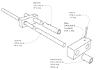
The cross bar and guide assembly is next. The bar slides through a mortise in the post with a clamp block to hold it in place once adjusted. This design allows you to use multiple sizes of saw frames should you choose. Draw boring and pegging the joints eliminates the need for clamps as the glue sets. Pegs from purple heart make it clear how the joint is made. The brace does have a couple of hidden screws.


While it might seem like an unstable design the cross bar does not move once the clamp plate is secured. The two brace pivot blocks (one on each end of the guide bar) allow for adjustment of the saw frame -- one vertically and one horizontally.

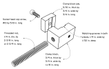
Last part to assemble is the saw frame, itself. It attaches to the guide rod assembly. The double-rod assembly allows the saw three-way motion -- front/back, up/down and left/right. The top rod pivots while the bottom rod slides through guide blocks. The French came up with a very clever design. The ornamental knob is not a handle of any sort. Instead, it is pressed against your shoulder as you tighten the saw clamp. It allows you to keep tension on the frame until the blade clamp is secure.


These are a couple of photos showing the fully-assembled chevalet. The front and back jaws each have an extra, sacrificial jaw with a "V". Over time these will need to be replaced as the saw occasionally cuts into these. Using the saw takes a bit of practice at first as it requires three separate actions. You press down with your heels to hold the work piece, rotate the piece with your left hand and work the saw with your right hand. It's like that trick where you're asked to rub your stomach and pat your head at the same time -- hard at first, but easier as you get the hang of it.


The first step was to make (or find) all the parts. You can make these out of any stable hardwood. I chose European beech, a traditional option. I through in a splash of purple heart to give my "chevy" a more stylish look.
Most of the non-wood parts are off-the-shelf items you can find at a hardware store. There are a few, however, you have to fabricate or have a machine shop do for you. I chose to make these as well and that is the contribution I made to the SAPFM article in the most recent (2023) APF Journal.
As you can see there are a lot of wooden parts to cut and shape. I was curious and counted around 30. No two are identical. Needless to say, I followed a plan and didn't try to work this out on my own. That would have taken considerably longer. I started last Spring, took a break to complete another project, then resumed the work in January.
I began by assembling the seat. It consists of two legs, a stretcher and the seat. A chevalet is like a tripod when complete. The seat is attached to the main post later. That gives it stability. Anywhere I used through tenons that were visible I used wedges of purple heart to add contrast. The front leg is square to the seat and the back leg has a six degree splay. Note the bolt in the last photo used to temporarily clamp the stretcher to the front leg. This is also a through tenon, but it is eventually covered when the front post is bolted to the seat.
The post is just an upside down "T". I used a double tenon with glue and wedges to secure the post to the base. No clamps are necessary as the wedges hold the joint tight as the glue sets. The purple heart here is foot pads when in use. The last photo shows how the post and the seat will be joined. I've added the moving jaw to the front of the seat at this time.
The column and pressure bar are the next parts to assemble. The column fits into a recessed mortise in the seat and is bolted up through the seat. I used 1/2" bolts with square nuts. In most cases the square nuts fit into cavities so they cannot turn and are unseen. The pressure bar will eventually be held in place with a 3/8" steel pin. Note the spacer blocks and through bolts that hold the front post to the seat assembly. Removing these two bolts separates the two.
Next up is to assemble the foot bar. The bar is held in place by a retainer. A chain running through the seat connects the pressure bar to the foot pedal. As you press down on this bar (with your heels) it pulls the pressure bar down, causing the front jaw to squeeze toward the back jaw. This action holds the work in place as you saw. Roller bearings moving over a wear plate keep the action smooth.
The cross bar and guide assembly is next. The bar slides through a mortise in the post with a clamp block to hold it in place once adjusted. This design allows you to use multiple sizes of saw frames should you choose. Draw boring and pegging the joints eliminates the need for clamps as the glue sets. Pegs from purple heart make it clear how the joint is made. The brace does have a couple of hidden screws.
While it might seem like an unstable design the cross bar does not move once the clamp plate is secured. The two brace pivot blocks (one on each end of the guide bar) allow for adjustment of the saw frame -- one vertically and one horizontally.
Last part to assemble is the saw frame, itself. It attaches to the guide rod assembly. The double-rod assembly allows the saw three-way motion -- front/back, up/down and left/right. The top rod pivots while the bottom rod slides through guide blocks. The French came up with a very clever design. The ornamental knob is not a handle of any sort. Instead, it is pressed against your shoulder as you tighten the saw clamp. It allows you to keep tension on the frame until the blade clamp is secure.
These are a couple of photos showing the fully-assembled chevalet. The front and back jaws each have an extra, sacrificial jaw with a "V". Over time these will need to be replaced as the saw occasionally cuts into these. Using the saw takes a bit of practice at first as it requires three separate actions. You press down with your heels to hold the work piece, rotate the piece with your left hand and work the saw with your right hand. It's like that trick where you're asked to rub your stomach and pat your head at the same time -- hard at first, but easier as you get the hang of it.