
(I changed text size per request)
There was a thread last March asking for help in raising a drill press table with lots of good suggestions. I replied with my potential solution using a linear actuator that I had acquired. I said when I got it done I would post the results. The idea for this is not mine I saw it in a magazine a long time ago.
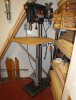
My drill press is a floor model Craftsman from the early 70’s that I purchased new. I added a large table top to it immediately after purchase. As I mentioned it has become really difficult to reach around the back, unlatch it and move the table. This last Monday I decided to implement the lift project. I finished up in two days and it was operational.
The specs on the actuator are it is 115V, 500LB lift capacity, 18” travel, cost me $70 on ebay 4 years ago. It had a built in set of limit micro switches for controlling the stroke travel. For some reason these actuators’ come without capacitors, so you need to get one matched to the unit from any electric supply house, mine cost $6.
To install the actuator I made a bracket for the base and a bracket on the table. I used what I had on hand in my scrap bin. I do a lot of metal working so my scrap bin has lots in it.
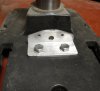
For the base I used 2” x 2” x ¼”angle Aluminum. I would have used only one bolt to hold it in place, however, there was a rib directly in the center of the base casting so I used two bolts. The hole to connect to the Actuator base and its height is dependent on what actuator you have. The design can be seen in the photo.
For the table I used 2 pieces of 2” x 2” x ¼” angle attached to the side of the table. I ran a piece of 1 ½ “ angle across the bottom of the table and attached to the support angle, see photos. In the center I made a stud from a bolt that matched the moving part of actuator see photos
I made sure that the distance out of the two mounts was the same so the actuator would be parallel to the drill press column.
Since I was not going to need to rotate the table my mounting system does not allow for much rotational ability for the table. By placing the mounting bolts in the position in the photos ie perpendicular to the column and leaving about .050 play when tightening the stud bolts I have about 4” of table rotational movement. I sketched up a lift bracket that would have allowed complete rotation of the table around the column, but was a lot of work and I did not need the capability.
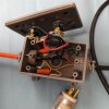
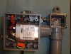
I wired up the main box on the motor with the capacitor as can be seen in the photo. My up / down box is also shown with two push buttons – up and down. I had the boxes and switches as left overs from other projects, my guess is about $15. I included a schematic in a PDF file.
I did not build an interlock to keep me from pushing the lift buttons if the table was locked. I had a small micro switch I could have mounted so it touched the end of the bolt that locks the table. It would be open when the table was locked and closed when unlocked. If this becomes an issue I will install it.
I had more travel than needed. It is apparent I could have used a unit with 14” or 16” stroke rather than the 18”. If you do one just figure what travel you need. The bottom bracket could be modified to account for different units.
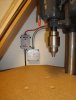
I adjusted the up limit switch to stop up travel about ½” from the chuck. In my case the drill press chuck is a 633C. The drill press spindle is a 33JT with locking threads. The 633C chuck has a 33 JT and a locking collar. This chuck allows you to use things like sanding drums and not have the chuck come off the taper because of side pressure. Craftsman sold other spindle attachments that had locking collars for using the drill press with lateral force on the spindle. One attachment allowed use of shaper cutters. This is why I adjusted the up so close to the chuck.
I just got it done so all I can say at this point is, given it only took two days, I should have done it 4 years ago when I got the actuator!
Bob
There was a thread last March asking for help in raising a drill press table with lots of good suggestions. I replied with my potential solution using a linear actuator that I had acquired. I said when I got it done I would post the results. The idea for this is not mine I saw it in a magazine a long time ago.
My drill press is a floor model Craftsman from the early 70’s that I purchased new. I added a large table top to it immediately after purchase. As I mentioned it has become really difficult to reach around the back, unlatch it and move the table. This last Monday I decided to implement the lift project. I finished up in two days and it was operational.
The specs on the actuator are it is 115V, 500LB lift capacity, 18” travel, cost me $70 on ebay 4 years ago. It had a built in set of limit micro switches for controlling the stroke travel. For some reason these actuators’ come without capacitors, so you need to get one matched to the unit from any electric supply house, mine cost $6.
To install the actuator I made a bracket for the base and a bracket on the table. I used what I had on hand in my scrap bin. I do a lot of metal working so my scrap bin has lots in it.
For the base I used 2” x 2” x ¼”angle Aluminum. I would have used only one bolt to hold it in place, however, there was a rib directly in the center of the base casting so I used two bolts. The hole to connect to the Actuator base and its height is dependent on what actuator you have. The design can be seen in the photo.
For the table I used 2 pieces of 2” x 2” x ¼” angle attached to the side of the table. I ran a piece of 1 ½ “ angle across the bottom of the table and attached to the support angle, see photos. In the center I made a stud from a bolt that matched the moving part of actuator see photos
I made sure that the distance out of the two mounts was the same so the actuator would be parallel to the drill press column.
Since I was not going to need to rotate the table my mounting system does not allow for much rotational ability for the table. By placing the mounting bolts in the position in the photos ie perpendicular to the column and leaving about .050 play when tightening the stud bolts I have about 4” of table rotational movement. I sketched up a lift bracket that would have allowed complete rotation of the table around the column, but was a lot of work and I did not need the capability.
I wired up the main box on the motor with the capacitor as can be seen in the photo. My up / down box is also shown with two push buttons – up and down. I had the boxes and switches as left overs from other projects, my guess is about $15. I included a schematic in a PDF file.
I did not build an interlock to keep me from pushing the lift buttons if the table was locked. I had a small micro switch I could have mounted so it touched the end of the bolt that locks the table. It would be open when the table was locked and closed when unlocked. If this becomes an issue I will install it.
I had more travel than needed. It is apparent I could have used a unit with 14” or 16” stroke rather than the 18”. If you do one just figure what travel you need. The bottom bracket could be modified to account for different units.
I adjusted the up limit switch to stop up travel about ½” from the chuck. In my case the drill press chuck is a 633C. The drill press spindle is a 33JT with locking threads. The 633C chuck has a 33 JT and a locking collar. This chuck allows you to use things like sanding drums and not have the chuck come off the taper because of side pressure. Craftsman sold other spindle attachments that had locking collars for using the drill press with lateral force on the spindle. One attachment allowed use of shaper cutters. This is why I adjusted the up so close to the chuck.
I just got it done so all I can say at this point is, given it only took two days, I should have done it 4 years ago when I got the actuator!
Bob
Attachments
-
 Intallation-Complete-Closeup.jpg115.7 KB · Views: 141
 -
 Installation-Complete.jpg116 KB · Views: 148
 -
 Up-Down-Box.jpg106.1 KB · Views: 147
 -
 Control-Box-and-Limit-Switches.jpg114.2 KB · Views: 145
 -
 Base-Bracket.jpg108.9 KB · Views: 147
 -
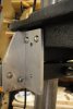 Table-Bracket-2.jpg96 KB · Views: 157
 -
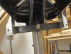 Table-Bracket-1.jpg94.1 KB · Views: 139
 -
Drill Press Lift Schematic.pdf24 KB · Views: 124
Last edited: