Hi I am not good electrical man, but I can implement some scheme with relay and sensors. Potentially use something like arduino (to implement delays on/off)
In my garage shop I don't have fixed places for each tool - I move it around on mobile bases. And use simple HF DC,
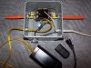
What I think I need: dedicated poser outlet (1 or 2) for "active tool" and outlet for DC. So for each operation I'll connect active tool in right outlet as well as connect DC hose to active tool dust port.
Base on my google something like this should work for me
https://www.bytesizedengineering.com/projects/shop-vac-auto-switch
What do you think?
When planning which tools you would want to use with such a device, be aware that a typical residential 120VAC receptacle is only rated for 15A max (this is the maximum rating for that style plug and receptacle per receptacle, the actual circuit itself may be either 15A or 20A depending upon your circuit breaker and house/shop wiring). Many shop vacs and 120VAC Dust Collectors can come very close to maxing out that amperage with typical (real) motor ratings usually in the 10-13A range for just the shop vac or DC alone, not including whatever other tool you were planning to use. In a pinch you can reduce the amp draw of a shop vac or DC by significantly choking off the airflow, such as by using long or undersized hose (you will here the motor speed up due to the reduced load since it is then moving much less air), but then you are also sacrificing effectiveness substantially since effectiveness is heavily dependent upon the volume of air moved.
I really wish these auto-switches better explained the inherent current limitations imposed by powering both the shop vac or DC off the same physical receptacle and circuit as the power tool as I’ve never felt that they make adequately clear that their typical 15A rating applies to the sum of both devices collectively and not 15A per device (where you see higher end shop vacs with such auto-switches built-in they typically monitor tool current needs and dynamically reduce the power output of the shop vac in an effort to stay within the 15A power budget — but a “dumb” shop vac or DC obviously does not have the necessary brains to modify its power requirements dynamically).
If you have a 20A circuit then you could replace the 15A receptacle and plug with their 20A variant (NEMA 5-20P/R) to gain a few more usable amps (provided that no other electrical devices are sharing that same circuit) without overloading either the plug or receptacle (a 20A 120VAC plug or receptacle has one prong rotated 90°, or horizontal, relative to the other). But double-check the ratings of the auto-switch as many are only rated for 15A total load, in part because that is all they can be properly rated for when using a 15A plug (NEMA 5-15P/R) and receptacle.
But keep in mind that routers may present up to a 10-15A load of their own, a tablesaw is also typically around 13A, a jointer or thickness planer similarly, and a 1HP 120VAC DC may draw up to 10-12A, so you can run out of available amperage quite quickly when your shop vac or DC are also plugged into the same electrical circuit as the power tool since many power tools can present very high loads of their own under load. If there are any other electrical devices also drawing power off that same physical circuit (e.g. chargers, refrigerator/freezer, etc.) then their collective amperage must also be subtracted from what is otherwise available from the maximum 15A or 20A afforded by the circuit and breaker.
This is why why it is very advantageous to have one’s shop wired with multiple (at least 2) 120VAC and/or 240VAC so that the heavy load of a DC or shop vac may be plugged into one circuit and the tool into the other.
If you do have at least two electrical circuits to work with
then there is still a way to use such a power tool current sensor/auto-switch without risking overloading a single circuit. If you adapt the external contactor (heavy duty motor-rated relay) modification used earlier in this thread with the remote switch then you can use this auto switch to sense your power tool load, but instead of trying to directly power the DC or shop vac off the auto-switch you instead use the auto-switch to activate the contactor coil (closing/activating the contactor) and then connect the switched contactor contacts to an outlet on an entirely different circuit and connect your DC or shop vac such that it is switched by the contactor rather than directly through the auto-switch itself. By separating these two heavy loads and placing each on its own dedicated circuit you do not risk overloading either since neither circuit should ever see more than 15A each — yet you still get to enjoy the convenience afforded by such a device. Alternatively, this also would allow 120VAC power tools to automatically switch a larger 240VAC dust collector simply by connecting the contactor to a 240VAC receptacle instead (but the contactor coils would remain 120VAC as they are powered by the 120VAC auto-switch accessory).
Good luck with your project and be sure to let us know how things work out for you and what way you ended up choosing to go once you have implemented your idea.


")