
relief
-
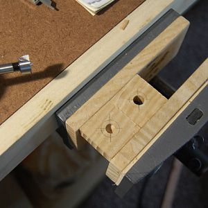
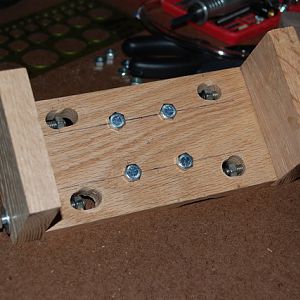
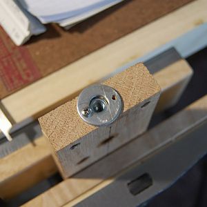
PIC 23 - Step 5i
Closeup of a screw in the Horizontal Stabilizer- MT native
- Media item
- carving drill foredom homemade jig press relief
- Comments: 0
- Album: Homemade Relief Carving Jig
-
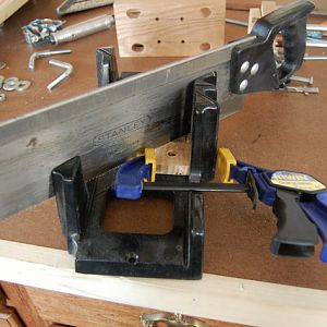
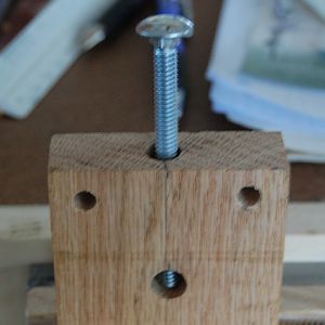
PIC 22 - Step 5i
Pre-drill for the screws that will secure the Guides horizontally- MT native
- Media item
- carving drill foredom homemade jig press relief
- Comments: 0
- Album: Homemade Relief Carving Jig
-
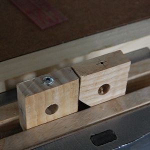
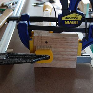
PIC 21 - Step 5h
Trim the corner of one of the Stabilizers to add clearance for the Depth Adjustment Rod- MT native
- Media item
- carving drill foredom homemade jig press relief
- Comments: 0
- Album: Homemade Relief Carving Jig
-
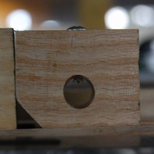
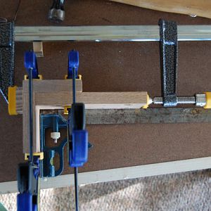
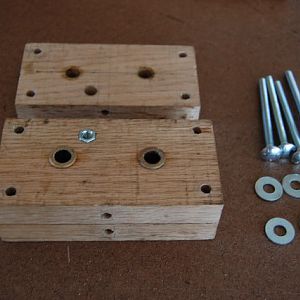
PIC 20 - Step 5g
Cut two (2) pieces for the Horizontal Stabilizers 1.5in x 1.5in and drill min 3/8in dia holes in centers for the Guides- MT native
- Media item
- carving drill foredom homemade jig press relief
- Comments: 0
- Album: Homemade Relief Carving Jig
-
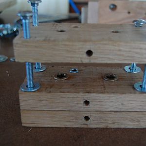
PIC 19 - Step 5d
Z-axis Support dry fit - four bolts in center for attachment to the Floor Flange on the Frame- MT native
- Media item
- carving drill foredom homemade jig press relief
- Comments: 0
- Album: Homemade Relief Carving Jig
-
PIC 18 - Step 5b
Square the back (‘spine’) and ends of Z-axis Support before drilling pocket-holes - end view- MT native
- Media item
- carving drill foredom homemade jig press relief
- Comments: 0
- Album: Homemade Relief Carving Jig
-
PIC 17 - Step 5b
Square the back and ends of Z-axis Support before drilling pocket-holes - side view- MT native
- Media item
- carving drill foredom homemade jig press relief
- Comments: 0
- Album: Homemade Relief Carving Jig
-
PIC 16 - Step 4b
Closeup of Foredom Hanger - FOLLOWUP - DO NOT USE ANYTHING ON HANGERS!!!! MESSY, STICKY, GOOEY YUCK!- MT native
- Media item
- carving drill foredom homemade jig press relief
- Comments: 0
- Album: Homemade Relief Carving Jig
-
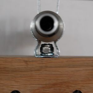
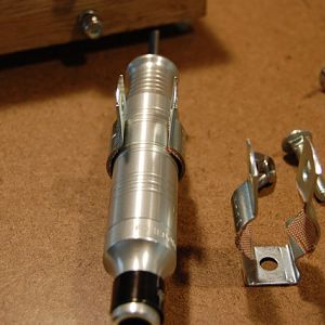
PIC 15 - Step 4a
Place the Foredom Handpiece in the Hangers and check to make sure there is clearance between the end of the carriage bolt and the Handpiece- MT native
- Media item
- carving drill foredom homemade jig press relief
- Comments: 0
- Album: Homemade Relief Carving Jig
-
PIC 14 - Step 3e
Dry Fit the Handle(s) into the Middle Section of the Carriage. Trim off the excess tubing- MT native
- Media item
- carving drill foredom homemade jig press relief
- Comments: 0
- Album: Homemade Relief Carving Jig
-
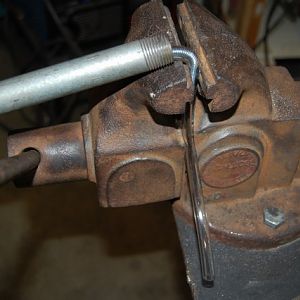
PIC 13 - Step 3d
Insert the 4in piece into 1/4in I.D. Vinyl Tubing and bend in a vise to make the Locking Handle- MT native
- Media item
- carving drill foredom homemade jig press relief
- Comments: 0
- Album: Homemade Relief Carving Jig
-
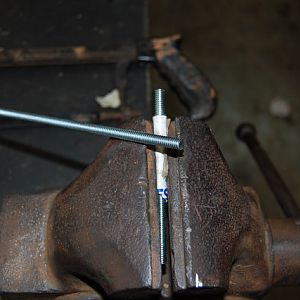
PIC 12 - Step 3c
Cut a 4in piece from 1/4in-20 x 36in long Threaded Rod. I used a Hack Saw- MT native
- Media item
- carving drill foredom homemade jig press relief
- Comments: 0
- Album: Homemade Relief Carving Jig
-
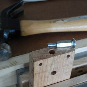
PIC 11 - Step 3b
Screw a flat washer over Coupling Nut to keep the Nut from working out when under locking pressure- MT native
- Media item
- carving drill foredom homemade jig press relief
- Comments: 0
- Album: Homemade Relief Carving Jig
-
PIC 9 - Step 2f
Assemble the Carriage - Add four (4) Flat Washers, the same thickness as Bushing flanges, between the sections so the Carriage will be square and level- MT native
- Media item
- carving drill foredom homemade jig press relief
- Comments: 0
- Album: Homemade Relief Carving Jig
-
PIC 8 - Step 2e
Drill holes in the side(s) (Middle Section only) for the Locking Handle Coupling Nut(s)- MT native
- Media item
- carving drill foredom homemade jig press relief
- Comments: 0
- Album: Homemade Relief Carving Jig
-
PIC 7 - Step 2d
Re-drill (Middle Section only) to allow for O.D. of the Flanged Bushings and the Coupling Nut- MT native
- Media item
- carving drill foredom homemade jig press relief
- Comments: 0
- Album: Homemade Relief Carving Jig
-
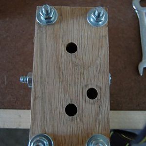
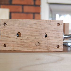
PIC 6 - Step 2b
Four (4) holes for clamping, two (2) for the Guides and one (1) for the Depth Adjustment Rod- MT native
- Media item
- carving drill foredom homemade jig press relief
- Comments: 0
- Album: Homemade Relief Carving Jig
-
PIC 10 - Step 3a
Insert the Coupling Nut as perpendicular as possible by using a bolt as a visual aid- MT native
- Media item
- carving drill foredom homemade jig press relief
- Comments: 0
- Album: Homemade Relief Carving Jig
-
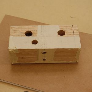
PIC 5 - Step 2a
BEFORE YOU DRILL Use masking tape to bind the pieces together to ensure hole alignment- MT native
- Media item
- carving drill foredom homemade jig press relief
- Comments: 0
- Album: Homemade Relief Carving Jig
-
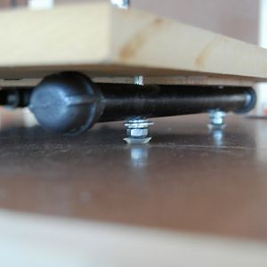
PIC 4 - Step 1i
Table bolted to frame with rubber Bumpers for feet and shim to prevent MDF flexing- MT native
- Media item
- carving drill foredom homemade jig press relief
- Comments: 0
- Album: Homemade Relief Carving Jig
Premier Sponsor
Our Sponsors
LATEST FOR SALE LISTINGS
-
-
 SOLD -- $75: Gast moa v113 Vacuum Pump Veneer, 60" bag and board
- Started by peterdnight
- Replies: 1
-
GONE: Gladiator 5 cleats, 10 hangers, Paper Towel and Shelf
- Started by peterdnight
- Replies: 3
-
SOLD -- $100 Makita mac700 portable air + grex pin nailer + 2 others + 50' hose
- Started by peterdnight
- Replies: 1
-